Ideal Transformer
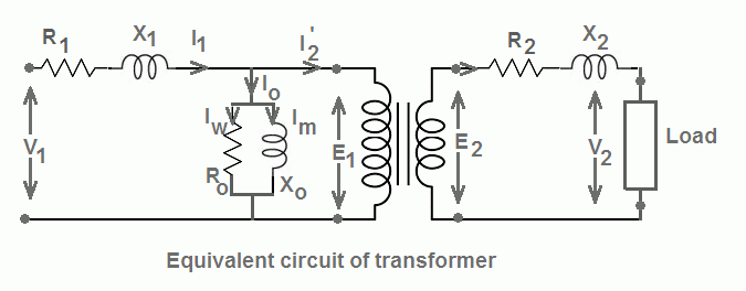
The transformer has two winding - primary and secondary winding. The winding has resistance and the reactance. The equivalent circuit of a practical transformer is as given below.

The resistance and reactance of the winding must be as minimum as possible to have low power losses. However, it is only imaginary that winding has zero resistance and reactance.
Definition of an Ideal Transformer
An ideal transformer is a imaginary transformer which has ;
Definition of an Ideal Transformer
An ideal transformer is a imaginary transformer which has ;
- Zero Copper loss - Copper loss of an ideal transformer is zero because the winding resistance of the primary and the secondary is zero. This means that both the winding are pure inductive in nature.
- Zero leakage flux - The leakage flux is part of the main flux which does not link to secondary winding of the transformer. In an ideal transformer, it is assumed that the entire flux produced in the primary gets linked to the secondary and thus the entire flux produced in the primary is fully utilized.
- Zero Iron loss - It is assumed that an ideal transformer has a core of infinite permeability. An ideal transformer takes very less magnetizing current to set up flux in the core.
- 100% Efficiency - If a transformer fulfills above three criteria the losses- eddy current, hysteresis and copper loss is zero and the transformer delivers output power equal to the input power.However, this is hypothetical condition and transformer or any equipment can;t be 100 % efficient.
Ideal Transformer Model
The equivalent circuit of an ideal transformer is as given below.
When voltage V1 applied to primary, the counter EMF(E1) induced across the primary which opposes the primary voltage. The counter EMF lags the applied voltage by 180 electrical degree.
The transformer draws more current at the instant of switching on of the transformer because the back EMF induced in the primary is zero. The transformer draw magnetizing current to produce the counter EMF in the primary. The magnetizing current lags the applied voltage by 90 degree. This current is called the magnetizing current Iμ .
The alternating magnetizing current set up the alternating flux in the core and the flux produced is proportional to the magnitude of the magnetizing current and in the phase with the current. The flux produced in the primary gets linked to the secondary and induce E2 voltage. The induced voltage E2 in the secondary is equal to the output voltage V2 of the secondary.


Comments
Post a Comment