Harmonic Restraining in Differential Protection
The differential relay is used for protection of transformer ,alternator and large
rating HT motor. The differential protection scheme is also known as a
zone protection. The relay must trip in case of the fault in the
winding of the transformer. If the fault is outside of the zone,the
differential relay must remain inoperative.
The transformer draws a large current at the time of switching on of the transformer at no load. The large
current drawn by the transformer is known as inrush current or
magnetizing inrush current, The magnitude of the inrush current may be 8
to 10 times or even larger than this. The magnitude and duration of
inrush current depends on the instant of the AC waveform at which the
transformer is switched on. The waveform of the transformer inrush
current is as given below.
 The
secondary current is zero and the primary current is high at the time
of charging of the transformer. This difference in current between
primary and secondary may lead to operation of differential protection
relay. Thus, it is not possible to charge the transformer. If the
protection relay is bypassed the differential protection of the
transformer will get defeated. Bypassing the differential protection
relay is not the solution.
The
secondary current is zero and the primary current is high at the time
of charging of the transformer. This difference in current between
primary and secondary may lead to operation of differential protection
relay. Thus, it is not possible to charge the transformer. If the
protection relay is bypassed the differential protection of the
transformer will get defeated. Bypassing the differential protection
relay is not the solution.

The transformer generates 2nd and 5th order harmonic current at the time of charging because of non linear B-H characteristics
of magnetic flux. The magnetic flux in the core is not sinusoidal and
transformer generates harmonics. The sensing of the harmonics and
restraining the differential protection relay operation at the time of
charging of the transformer is one of the solution. This requirement is
fulfilled by harmonic restraining in differential protection of the
transformer.
If
we analyse the inrush current by Fourier series, it has 2nd and 5th
order harmonics. The 2nd order harmonic is rich when transformer draws
magnetizing current at the time of switching of transformer. The
frequency of the 2nd order harmonics is 100 Hz. The differential relay has a 100 Hz filter circuit which measures the frequency and the magnitude of the 2nd order harmonic current in the differential current.
If the relay senses the current of 100 Hz
frequency and if the current is more than the differential current
setting of the relay, the relay will observe that the transformer is
taking the inrush magnetizing current and the relay blocks its main tripping mechanism.
The setting of the 2nd order harmonic restraining is kept at 20-25 % of the differential relay setting. If the current is below the differential relay setting, the relay does not trip because the relay will observe it as a transformer charging phenomenon. If the harmonic restraining current is more than the differential relay setting, the relay will trip with differential protection fault.
During over fluxing of the transformer, the transformer current has predominant 5th order harmonic current. The differential protection relay will trip in case of the over fluxing. If the over fluxing happens for short period of time, the differential relay should not trip. Therefore, to prevent the operation of differential protection relay in case of the over fluxing, 5th order harmonic restraining is provided.
If the magnitude of the 5th order harmonic current is more than the the setting of the differential protection relay setting the relay will trip. If the magnitude of the 5th order harmonic current is less than the the setting of the differential protection relay setting the relay will not trip. The setting of the 5th order harmonic restraining is generally kept 20- 25 % of the differential relay setting.
The basic circuit of harmonic restraint relay is as given below.

Saturday, October 19, 2019
Single Phase Transformer and Applications of Single Phase Transformer
Transformer
transforms voltage from one level to other level without changing the
power and frequency. Transformer is a static electrical equipment and
it does not have any moving part. The transformer has a magnetic CRGO
steel core and two copper
winding, one act as a primary and other act as a secondary.The
transformer losses are very less because there is no moving part in the
transformer, thus transformer is a high efficiency equipment.The
transformer functions on the principle of Faraday;s law of
electromagnetic induction.

When AC voltage is applied to primary of a transformer, the counter emf is generated in the primary according to rate of change
of current. The counter emf generated in the primary limits the current
in the primary. The counter emf is zero if the DC is applied to the
primary and the transformer can't be operated with DC. The flux is
generated in the primary when alternating voltage is fed. The flux
travels through
the magnetic core and the alternating flux gets linked to the
secondary. The alternating flux induce AC voltage in the secondary.
The RMS value of the voltage induced in the winding depends on the frequency, number of turns and the flux.
Ep = 4.44 Np fФm
Es = 4.44 Ns fФm
Where,
Ep = Induced EMF in primary winding
ES = Induced EMF in secondary winding
Np = Number of turns in primary winding
Ns = Number of turns in the secondary winding
f = Frequency
Фm = Flux in the core
Es = 4.44 Ns fФm
Where,
Ep = Induced EMF in primary winding
ES = Induced EMF in secondary winding
Np = Number of turns in primary winding
Ns = Number of turns in the secondary winding
f = Frequency
Фm = Flux in the core
There
are two type of transformer single phase transformer and three phase
transformer. The working principle of the transformer is the same. The
single phase or three phase transformer can be used a step down or step
up transformer.
The single phase transformer has core and winding as its main part. The winding has resistance and to keep the transformer copper
loss down the winding material of small resistance value is selected.
The laminated core is used to keep the eddy current losses to minimum
value. The thin lamination of thickness 0.25 to 0.5 mm is used and the
laminated sheets are isolated from each other. The insulating varnish is
used for this purpose.
The
transformer 500 kVA and above are of generally oil filled type.The
transformer oil is used in the transformer tank for the insulation and
cooling purpose.
Application of Single phase Transformer
Single phase transformer is widely used in low voltage application.The single phase transformers are mostly used to step down the single phase supply 220 volts
to lower voltage. The transformer is used for power supply to
electronic equipment. The transformer is used in the AC/DC rectifier,
electronic circuits etc.


Friday, October 18, 2019
Ideal Transformer
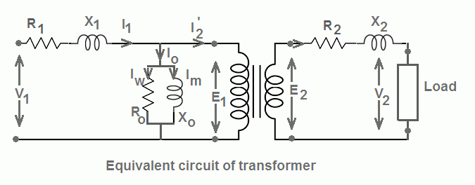
The transformer
has two winding - primary and secondary winding. The winding has
resistance and the reactance. The equivalent circuit of a practical
transformer is as given below.
The resistance and reactance of the
winding must be as minimum as possible to have low power losses.
However, it is only imaginary that winding has zero resistance and
reactance.
Definition of an Ideal Transformer
An ideal transformer is a imaginary transformer which has ;
Definition of an Ideal Transformer
An ideal transformer is a imaginary transformer which has ;
- Zero Copper loss - Copper loss of an ideal transformer is zero because the winding resistance of the primary and the secondary is zero. This means that both the winding are pure inductive in nature.
- Zero leakage flux - The leakage flux is part of the main flux which does not link to secondary winding of the transformer. In an ideal transformer, it is assumed that the entire flux produced in the primary gets linked to the secondary and thus the entire flux produced in the primary is fully utilized.
- Zero Iron loss - It is assumed that an ideal transformer has a core of infinite permeability. An ideal transformer takes very less magnetizing current to set up flux in the core.
- 100% Efficiency - If a transformer fulfills above three criteria the losses- eddy current, hysteresis and copper loss is zero and the transformer delivers output power equal to the input power.However, this is hypothetical condition and transformer or any equipment can;t be 100 % efficient.
Ideal Transformer Model
The equivalent circuit of an ideal transformer is as given below.

When voltage V1 applied to primary, the counter EMF(E1) induced across the primary which opposes the primary voltage. The counter ? lags the applied voltage by 180 electrical degree.

The transformer draws more current at the instant of switching on of the transformer because the back EMF induced in the primary is zero. The transformer draw magnetizing current to produce the counter EMF in the primary. The magnetizing current lags the applied voltage by 90 degree. This current is called the magnetizing current Iμ .

The alternating magnetizing current set up the alternating flux in the core and the flux produced is proportional to the magnitude of the magnetizing current and in the phase with the current. The flux produced in the primary gets linked to the secondary and induce E2 voltage. The induced voltage E2 in the secondary is equal to the output voltage V2 of the secondary.

Tuesday, October 15, 2019
Shell Type Transformer
The transformer can be categorized into core type transformer and shell type transformer
depending on the construction of the magnetic core and arrangement of
the winding of the transformer. In the shell type transformer the core
encircles the winding.
Core of Shell Type Transformer
The core of the shell type transformer is made from the E-I and E-E type laminated sheet.
Core of Shell Type Transformer
The core of the shell type transformer is made from the E-I and E-E type laminated sheet.

The core of the single phase shell type
transformer has three limbs.This arrangement increase the mechanical
strength of the core and also the winding remain protected from the
mechanical shock.
Winding of Shell Type Transformer
The HV and LV winding is wound around the central limb and the central limb carries the entire flux (Ф ) and the side limbs carries the half (Ф/2 )of the total flux(Ф ).That is why the cross section area of the central limb is two times of the cross section area of the side limbs.The arrangement of the winding in a shell type transformer around the central limb is as given below.

The magnetic flux flows through two
closed magnetic path and therefore the losses gets reduced and the
efficiency of the transformer improves. The shell type transformer gives
more output as compared to similar core type transformer. The core also
provides better mechanical support to winding and under short circuit
condition the electromagnetic force developed has less effect on the
winding.
The HV and the LV winding is wound around the central limb in the sandwich arrangement. The HV winding is sandwiched between LV winding.

The quantity of the conductor required for the shell type transformer is less because both the winding are wound on the central limb. However, the insulation requirement is more as compared to the core type transformer because HV and LV winding is wound alternatively on the same limb. The design of the shell type transformer is complex compared to the core type transformer.
In case of any defect in the inner winding of shell type transformer, all the outer winding need to be removed for repairing or rewinding.
Cooling of Shell Type Transformer
In case of core type transformer natural air cooling may be sufficient. However, the forced air or forced oil cooling is required in a shell type transformer because the winding is surrounded by yoke and limbs.
Applications of Shell Type Transformer
The shell type transformer is used for the low voltage applications and are generally used in low voltage power circuits and electronic circuits.The cost of the shell type transformer for low voltage applications is less because the square or rectangular cross section area core can be used.
Due to complexity of the construction, the shell type transformer requires special fabrication facilities which increase the cost of productio
Transformer Rating
The maximum current that transformer can
deliver to loads as known as the current rating of the transformer. The
voltage, maximum current delivery of the transformer and the product of
the voltage and maximum current known as VA rating are engraved in the nameplate of the transformer.

The rating of the transformer is
adversely affected with abnormal temperature rise caused by the losses.
The no load losses increases with an increase in the frequency and or
voltage and the copper loss increase if the load power factor is more
lagging which demands more current from the transformer and the copper
loss gets increased. The losses can be kept within the limit by
maintaining the rated voltage ,frequency and load current.
The losses cause temperature rise of the
transformer and if transformer is operated above its rated safe
temperature limit, the winding insulation is apt to fail. The
temperature can be held within the safe limit by proper cooling.
The losses depends on the V and I. The
rating of the transformer depends on the losses. The losses are
independent of the power factor that is why the rating of the
transformer does not depend on the load and it depends on the V x I
which is known as VA rating of the transformer. The
designer designs the transformer taking into account the maximum VA
rating of the transformer. The transformer is specified for apparent
power rating- VA rating.
The transformer primary VA is equal to
the secondary VA plus the losses in the transformer. If the losses
increase, the secondary VA delivery will get affected because of the
temperature rise of the transformer. Generally the losses of the
transformer is negligible the primary VA is equal to the secondary VA.
The VA rating marked on the nameplate is
applicable for both the winding and VA rating of both the winding of
transformer is the same. For a 440/220 Volts, 100 KVA transformer, the
primary winding VA is 100 kVA and the secondary winding kVA is also 100
kVA.
Comments
Post a Comment