Back EMF and its Significance in DC Motor
When the DC voltage is applied to the armature of the DC motor,the motor draws enormously high current at the starting time and it decrease as the motor accelerates.Why the DC motor draws high armature current at the starting and how the current get decreased as the motor accelerates is because of the counter potential force developed across the armature winding. The counter voltage induced across the armature winding is called the back EMF. The diagram of the separately excited DC motor is as given below.

The DC motor has two main parts- the armature and the field winding. The field current flowing in the field coil generates the flux in the motor. The flux get linked to the armature conductor. when the motor armature( A rotating part) is stationary, the flux of constant magnitude linking to the armature conductor does not produce the voltage in the armature conductor.Therefore, the back EMF is zero when the motor starts. When the motor starts accelerating the back EMF starts developing across the armature winding. The induced EMF opposes the applied voltage according to the Lenz's law.
The magnitude of the counter EMF or back EMF depends on the followings;
- The field flux
- The Speed of the motor
- No. of conductors in the armature winding
The equation of the back EMF is as given below.
Eb= ΦNZ/60 *P/A
Where, Φ = Flux /Pole
N = Armature Speed
Z = Total number of armature conductor
A = Number of parallel paths in the armature winding
The back EMF is proportional to the speed of the motor.

At start when N=0, Eb=0 and the motor draw very high armature current. Due to an interaction of the field flux and the armature current the torque is produced.
T= K*Φ Ia
The torque is exerted on the armature and motor starts accelerating. The back EMF starts to develop as the motor accelerates because the back EMF is proportional to the speed of the motor. The magnitude of the back EMF is always less than the applied DC voltage because IaRa drop in the armature.
Eb= (V-IaRa)
How Back EMF regulates the flow of armature current?
Case 1: When the applied armature is increased
The back EMF limits the armature current and make the motor self regulating. If the applied voltage is increased the armature current increase momentarily and the speed of the motor increase. The increased speed of the motor increases the back EMF and the armature current gets reduced.
Case 2: When the speed gets decreased
Eb= (V-IaRa)
Ia= (V-Eb)/Ra
If the speed of the motor gets decreased because of the increased loading, the driving torque becomes less than the load torque and motor slow down and the back EMF gets decreased.The decreased back EMF will allow the more armature current to flow in the armature winding.The increased armature current will produce more torque which will produce the torque required by the load.When the motor attains the normal speed the back EMF will get reduced and thus the armature current get reduced. Thus the self regulation of the armature current is achieved.
Case 3: When the speed gets increased
If the load on the motor is decreased, the driving torque becomes more than the load torque and, the motor speed increases and the increased speed cause increase in the back EMF. The increased back EMF opposes the applied DC voltage and thus the armature current gets decreased.The motor stops accelerating and the speed again bring back to the point that meets the exact load requirement.
Thus the back EMF regulates the armature current according to the load requirement.
Why DC Series Motor should not be Started at No Load

In DC series motor, the field and armature winding is connected in the series and, both winding carries the same amount of current.The field winding has to carry the full rated armature current, therefore the field coil has few turns of thicker wire.
The speed of the DC motor is proportional to the back EMF(Eb) and inversely proportional to the flux. The flux is proportional to the field current. In the DC series motor the field current and the armature current is same. Therefore, the flux in the motor is proportional to the armature current(Ia).
N=K1*Eb/Φ ----------(1)
N= Speed of the motor
Eb= Back EMF of the armature
Φ= Flux
K= constant
When the armature current flows, the armature inductance opposes the flow of the current. The voltage of the opposite polarity to applied voltage(V) is induced in the armature to impede the armature current. The voltage induced in the armature is known as the back EMF(Eb).
According to the Kirchoff's current law, the algebraic sum of all the voltage around any closed loop in a circuit is zero.
V+Ia(Ra+Rf)+Eb=0 -----------(2)
Ra= The armature resistance
Rf= The field resistance
V= Applied Voltage
Eb= V-Ia( Ra+Rf) ------------(3)
N=K1*Eb/Φ
Eb= NΦ --------------(4)
Putting the value of Eb of equation(4) in equation (3)
K1*NΦ= V-Ia( Ra+Rf)
N= [V-Ia( Ra+Rf)]/K1*Φ
N= [V-Ia( Ra+Rf)]/K1*K2Ia (Φ∝ If, or Φ∝ Ia as Ia=If) K2- Constant
N= [V-Ia( Ra+Rf)]/K1K2*Ia
N= V/K1K2*Ia-( Ra+Rf)]/K1K2
N= (V/K1K2)*1/Ia-( Ra+Rf)]/K1K2
N=K3*1/Ia-K4
Where K3(constant)=(V/K1K2)
K4(constant)=( Ra+Rf)]/K1K2
N=K3/Ia-K4 ---------(5)
From equation (5) it is clear that the speed of the motor is inversely proportional to the armature current.
The armature current v/s speed characteristics of the DC series motor is as given below.

At no load, the armature current of the DC series motor is very low. If the motor is operated at no load, the motor will attain the enormously high speed that can physically damage the rocker arm assembly and the motor parts. This is like the same case when the separately excited DC motor is started without switching on the filed supply.
When the DC series motor is connected to the load at the time of starting of the motor, the motor draws the more armature current compared to the starting current with motor operation at no load and the speed of the motor increases in the controlled way.The DC series motor must not be tested on no load condition.
In view of the above reasons, the DC series motor should not be started at no load
DC Shunt Motor : Construction, Speed Control & Characteristics
CONSTRUCTION OF SHUNT DC MOTOR

The field winding of DC shunt motor is wound with many turns to increase the flux linkage and the armature winding is designed to carry higher current. This is done because the torque is proportional to the armature current and the flux.
DC shunt motor is self-excited type motor because the field and armature winding are energized with the same DC supply.

The armature winding and the field winding are connected in parallel and DC supply is applied to both the winding.
DC Shunt Motor Equations
When the DC voltage (V) is applied to the field and armature winding, the back EMF (Eb) is induced in the armature winding which opposes the applied voltage.
The armature current
Ia= Eb/Ra
Where, Ra- The armature resistance, Eb- Back EMF
The applied voltage (V) is equal to the Ia*Ra voltage drop plus back EMF(Eb).
V = IaRa + Eb -----------(1)
Ia = Itotal- Ish ---------(2)
V = Eb+( Itotal-Ish)Ra -----(3)
The field current is ;
Ish= V/ Rsh ------------(4)
Where, Rsh- The Resistance of field winding
The field current remains constant for a fixed applied DC voltage(V).
Characteristics of DC Shunt Motor
Torque- Armature Current (T-Ia)characteristics :

If the applied voltage is kept constant the field flux remains constant. The torque of the DC motor is proportional to the product of the flux and the armature current.
Ta 𝝰 Φ Ia
Ta 𝝰 Ia ( Φ constant)
The characteristic of torque and armature current is a straight line from the origin. The shaft torque is always less than the gross torque. This is because of stray losses.
The heavy starting loads require more armature current, so shunt motor should not be started on heavy loads.
Speed- Armature Current(N-Ia) characteristics :

The speed of the motor is directly proportional to the back EMF(Eb) and reciprocal to the flux.
N α Eb / Ф
The back EMF(Eb)= V-Ia.Ra
With an increase in the armature current with a load, the back EMF decrease very small due to small IaRa voltage drop as armature resistance is very low. The flux also decreases with an increase in load current due to the armature reaction. Thus the ratio of Eb/Φ remains almost constant, and the speed of the motor is almost constant with an increase of armature current with loading. Therefore, the DC shunt motor is a constant speed motor.
Speed-Torque(N-T) characteristics :

The change in the speed of the motor is negligible with the torque.
How the DC Shunt Motor Maintains the constant Speed?
When the loading on the motor is increased the speed of the motor decreases momentarily. With the reduction in speed, the back EMF also gets reduced. The armature current increase because of the reduction of the back EMF.
Ia= (V-Eb)/Ra
The increased armature current produces more torque. The increased amount of torque increase the speed and provides compensation for speed loss on loading.
Thus the motor maintains the constant ratio of Eb/flux and maintains the constant speed.
DC shunt motor should not be started at heavy loads :
The DC shunt motor should not be started at load. The back EMF (Eb) is zero when the motor is started. The DC shunt motor draws large armature current because back EMF is zero at start. If motor is started at heavy load the armature current exceeds to a greater extent. The large armature current cause heating in the armature winding and the insulation of the armature winding might get failed.Therefore, the DC shunt motor should not be started at heavy loads.,
Why DC Series Motor is Used For Driving Heavy Loads?
Why DC series motor has high starting torque?
For driving the high inertia loads, higher starting torque is required. The loads like locomotive engines, bucket elevators demand higher starting torque for the motion from its standstill position.

Construction of DC Series Motor
The DC series motor has a field winding and the armature winding. Both the winding are connected in the series and the same magnitude of the current flows through both winding.
The field winding has few turns of thick wire as the full armature current pass through the field winding.


The DC series motor provides high starting torque because the field and armature winding are connected in the series and carry the same current.

The starting torque of the DC series motor is proportional to the square of the armature current. The armature current-Torque characteristics of the DC series motor is as given below.

That is why DC series motor is capable to produce high starting torque, and it is preferred for driving heavy loads.
The high inertia loads like cranes need a high starting torque. The DC series motor is used in cranes.
IR Compensation in DC Drive
IR Compensation in DC Drive
IR compensation method is used to provide the speed regulation in the DC drive. The DC drive increases the output voltage of the drive to maintain the speed of the drive. The block diagram of separately excited DC motor is as given below.

In DC drive, the speed of the DC motor is governed by regulating the DC voltage with controlling the firing angle of the SCRs. The speed of DC motor can be given with the following formula.
N=K * Eb /ø = K*( V-Ia* Ra)/ø -----(i)
Where, N = Speed of the motor,
Eb= Back EMF of motor
Ra= Armature Resistance
Ø= Field Flux
In separately excited DC motor the field flux is kept constant. The speed of DC motor is governed by controlling the armature voltage. The DC drive control the DC output voltage fed to the DC motor, however, as per equation (1) the speed of the motor is not exactly proportional to the armature voltage; the speed of the motor is proportional to the back EMF of the motor that is equal to (V- Ia*Ra).
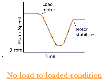
In the precise speed control applications like in weighing system, the RPM of the motor is controlled in the close loop to ensure desired speed accurately. The actual motor speed can be measured with a tachometer mounted on the motor shaft that gives the accurate speed measurement of the motor. The control scheme of the DC motor with speed feedback arrangement is as given below.

The speed control of DC motor can be achieved through controlling the armature voltage with changing the firing angles of silicon control rectifiers (SCRs). The speed of the motor can be measured with the tachometer mounted on the motor shaft or by measuring the armature voltage of the motor. The measurement with the tachometer gives the accurate measurement of the motor speed. The speed measured through tachometer is compared with the desired speed reference and the resultant error signal controls the firing angles of the SCRs. When the drive runs on tachometer feedback, IR compensation is not required as the drive increases voltage as per the set point of speed.
In case of failures of tachometer voltage feedback circuit, the drive system can be smoothly changed from tachometer to armature voltage feedback system. The armature voltage feedback as a speed feedback signal is the derived parameter for speed measurement of the DC motor; it does not give the accurate speed of the motor. The reason of error in measurement, as stated above, is because the speed of the motor is directly proportional to the back EMF. The back EMF of the DC motor can be calculated by subtracting the armature resistance drop (Ia*Ra) from the armature applied voltage. The DC drive calculates the IR drop of the motor from the mathematical algorithm stored in its microprocessor. The drive must be auto tuned with the DC drive controller when the motor is first commissioned. The drive stores all important motor parameters during the auto tuning process.
When the motor speed control feedback is changed from tachometer to armature voltage, the drive calculates the IR drop of the armature and firing angle of the SCRs is reduced to increase the armature voltage to compensate the IR drop of the armature. When the drive takes armature voltage as a speed feedback, the IR compensation is must to get the desired speed of the motor.
Starting Torque Of DC Motor

If the load demands higher torque than the maximum torque delivering of the motor,the motor will get stalled and will get overload tripped.The stall torque is the maximum torque at which the speed of the motor is zero. When the torque demanded by the load is more than the maximum torque delivering capacity, the speed of the motor will become zero or we can say the motor is not capable to rotate the mechanical load.
Torque Equation of DC Motor:
The torque of the DC Motor depends on the field flux and magnitude of armature current.
T=K*Φ*Ia
Where
T= Torque,
Φ=Flux,
Ia= Armature current
In a separately excited motor, the flux is constant so the torque of the DC motor depends on the armature current. The armature current of the DC motor is very high when the motor starts. The separately excited DC motor circuit diagram is as given below.T= Torque,
Φ=Flux,
Ia= Armature current

The back emf induced in the armature can be expressed as ;
Eb=V-Ia*Ra
When DC voltage is applied to the armature, the back EMF induced in the armature is zero, and the motor draws very high current.
The back EMF produced in the DC motor depends on the speed of the motor and the field flux. The back EMF of DC motor can be expressed by following mathematical formula.
Eb=ΦNZ/60 *(P/A) ------(1)
Where,
Eb= Back EMF induced in the armature
Φ =Main field Flux(Wb/m2)
N = Speed of the motor(RPM)
The torque produced by the DC motor is expressed by the following mathematical expression.
T=K* ΦIa ---------(2)
At starting, the back EMF is absent, as a result, the armature current is 5 to 6 times of the motor rated full load current, therefore, the starting torque of the motor is very high. That is why the armature voltage is increased gradually so that armature current can be limited to its safe operating range. The starting torque of the separately excited DC motor and shunt DC motor is less as compared to the starting torque of the DC series motor, however the separately excited DC motor and shunt DC motor are best suited for the application where speed regulation is required.
Starting torque of DC series motor:The back EMF produced in the DC motor depends on the speed of the motor and the field flux. The back EMF of DC motor can be expressed by following mathematical formula.
Eb=ΦNZ/60 *(P/A) ------(1)
Where,
Eb= Back EMF induced in the armature
Φ =Main field Flux(Wb/m2)
N = Speed of the motor(RPM)
The torque produced by the DC motor is expressed by the following mathematical expression.
T=K* ΦIa ---------(2)
At starting, the back EMF is absent, as a result, the armature current is 5 to 6 times of the motor rated full load current, therefore, the starting torque of the motor is very high. That is why the armature voltage is increased gradually so that armature current can be limited to its safe operating range. The starting torque of the separately excited DC motor and shunt DC motor is less as compared to the starting torque of the DC series motor, however the separately excited DC motor and shunt DC motor are best suited for the application where speed regulation is required.
The starting torque of the series DC motor is higher than the starting torque of the separately excited DC motor. The motor is used for the traction system.


T=K*ø*Ia
ø=K*Ia
T=K*I2a
 The torque of the DC series motor is proportional to the square of the armature current.That is why DC series motor has high starting torque. The DC series motor produces the highest torque among all kinds of motors.The DC series motor produces high starting torque as compared to starting torque of the separately excited DC shunt motor and the DC shunt motor. The DC series motor is used for driving the high inertia loads which demand higher starting torque.
The examples of high starting torque applications are rotary kiln, bucket elevator,railway traction etc.The DC series motor is the best motor for high starting torque to drive high inertia loads.That is why DC series motor is used for driving heavy loads.
Contrary to DC series motor, the starting torque of the DC shunt motor increase linearly with the armature current.
 The DC motor can deliver the highest torque among all types of DC motors; however, the speed regulation of the DC series motor is poor. The application where speed regulation is required the DC shunt motor or separately excited DC shunt motor is preferred.
One more thing about DC series motor is that it should never be started at no load.The motor can attain the enormously high speed if run on no load. The field current is less when the motor is operated at no load. The speed detection system can be used to detect the over speed of the motor and the over speed detection signal can be used to trip the DC drive.
Starting torque of DC Shunt motor:
 The DC shunt motor has field and armature winding. The field winding is connected in the parallel to the armature winding. That is why the motor is called DC shunt motor. The voltage across the both winding is the same.

The examples of high starting torque applications are rotary kiln, bucket elevator,railway traction etc.The DC series motor is the best motor for high starting torque to drive high inertia loads.That is why DC series motor is used for driving heavy loads.
Contrary to DC series motor, the starting torque of the DC shunt motor increase linearly with the armature current.

One more thing about DC series motor is that it should never be started at no load.The motor can attain the enormously high speed if run on no load. The field current is less when the motor is operated at no load. The speed detection system can be used to detect the over speed of the motor and the over speed detection signal can be used to trip the DC drive.
Starting torque of DC Shunt motor:
The connection of the field and armature winding is as shown below.

The DC shunt motor is best suited for the application where the speed regulation is required. The starting torque of the DC shunt motor is less compared to the starting torque of DC series motor. The flux in the motor remains constant and the motor delivers the constant torque.
The torque of the DC Motor is proportional to the field flux and the armature current. In the DC shunt motor the flux is constant, therefore the torque is proportional to the armature current.
T=K* ΦIa
T=K* Ia (Φ- Constant)
The armature current and torque graph of the DC shunt motor is as given below.

Comments
Post a Comment